212 Results
View results:
Sort by:

Creating a validation example for Computational Fluid Dynamics (CFD) is a critical step in ensuring the accuracy and reliability of simulation results. This process involves comparing the outcomes of CFD simulations with experimental or analytical data from real-world scenarios. The objective is to establish that the CFD model can faithfully replicate the physical phenomena it is intended to simulate. This guide outlines the essential steps in developing a validation example for CFD simulation, from selecting a suitable physical scenario to analyzing and comparing the results. By meticulously following these steps, engineers and researchers can enhance the credibility of their CFD models, paving the way for their effective application in diverse fields such as aerodynamics, aerospace, and environmental studies.
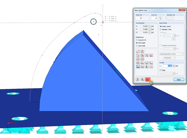
In RFEM, if you want to display a curved geometry (preferably in one continuous line), you can use splines or NURBS, for example. When modeling, you should pick the individual nodes one after another. If a mistake is made, you can go back using the special Undo function in the "New Spline Line" window. Thus, it is not necessary to enter the entire continuous line again.
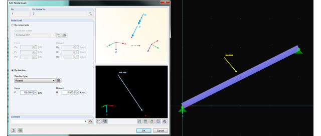
In RFEM and RSTAB, you can now rotate nodal loads or apply them on member axes. Thus, inclined members can also be loaded with nodal loads perpendicularly or along the member axis.
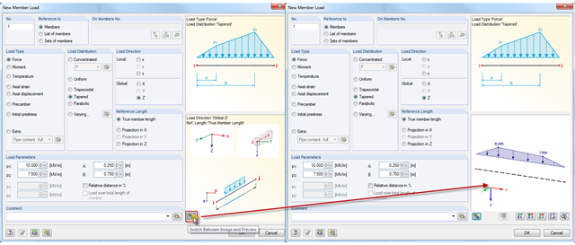
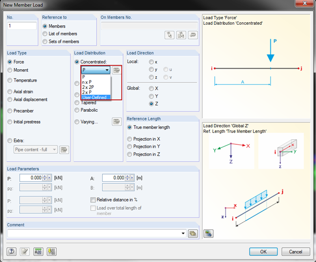
In addition to the load direction and reference length of member loads, it is now possible to display a preview of the loading.

Surfaces can be created using the "Surface via Line Extrusion" function by extruding lines perpendicular to the active work plane. The Video (WMV) shows how to use this function.
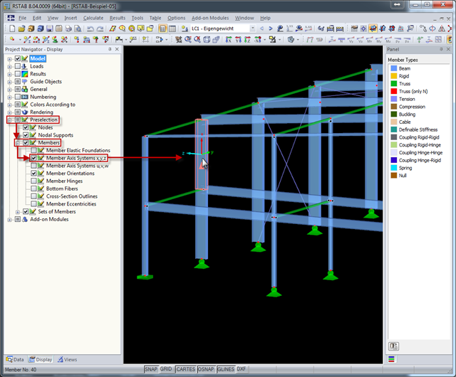
The local coordinate system of a member is particularly important when defining member end releases and member nonlinearities. The definitions follow the orientation of the axes. You can temporarily adjust the visibility of these member axes by means of preselection.
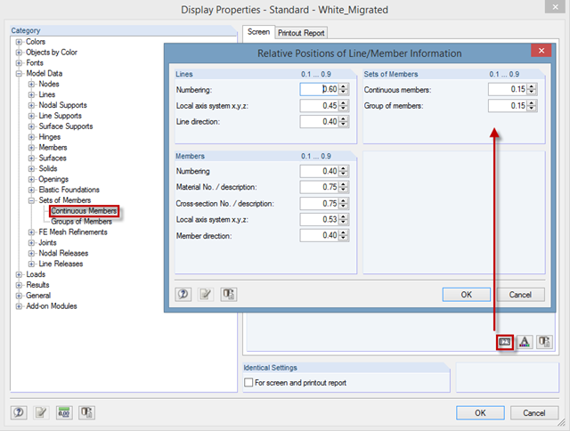
In RFEM and RSTAB, you can arrange the labeling of lines, members, and sets of members in a user‑defined way. To do this, open the dialog box in "Display Properties", where you can define the position of the information about the relative distance from the member start.
The equivalent loads determined in RF-TENDON due to prestress are transferred in RFEM as member loads or as line loads. A member load is used for member types with their own stiffness; a line load is used for member types without their own stiffness. In order to understand which values of the concentrated loads are to be transferred from RF‑TENDON to RFEM, you should use the following display settings: ~ Reference of the loads to the global coordinate system (GCS), ~ Load display: "Point"
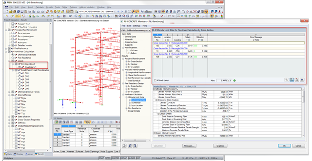
With RFEM 5.6.1103 and RSTAB 8.6.1103, there is an improved result output for the nonlinear calculation of reinforced concrete design in RF‑CONCRETE Members and CONCRETE. The new result windows include tables with a wide range of loading results; for example, governing load with the maximum ratio. In addition, you can now display the envelope results for the maximum ratio graphically.
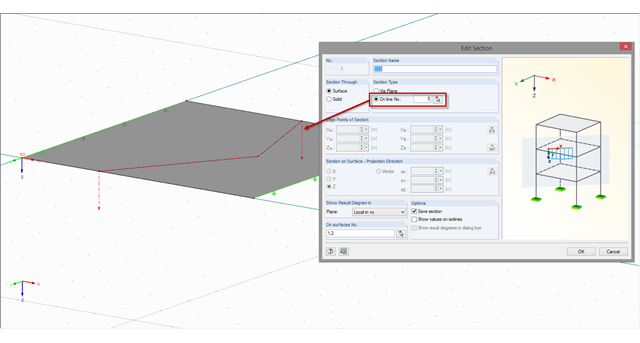
If a section is not on a straight line but on a curved or angled line, this line has to be defined accordingly as a polyline or a curved line. You can define the section along a line using the "Create Section Numerically" function.
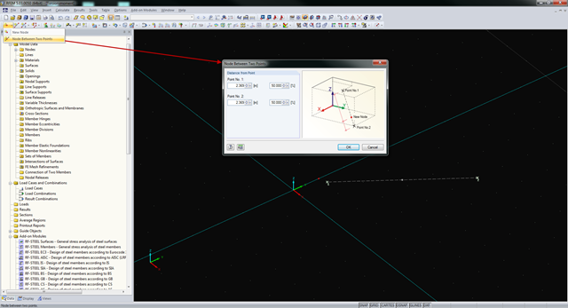
In RFEM and RSTAB, you can create nodes not only by means of coordinates, but also by means of existing nodes. You can use the "Node Between Two Points" function to create a node located on an imaginary line connecting two nodes. You can enter the distance as a percentage or according to the relative lengths.

For the stability verification of members using the equivalent member method, it is necessary to define effective or lateral-torsional buckling lengths in order to determine a critical load for stability failure. In this article an RFEM 6-specific function is presented, by which you can assign an eccentricity to the nodal supports and thus influence the determination of the critical bending moment considered in the stability analysis.
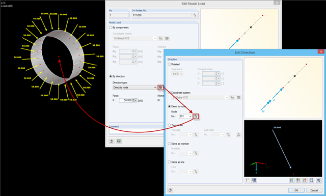
When defining nodal loads, you can rotate the load using several simple options: ~ Rotation by angle around the global coordinate axes in a specific order, ~ Alignment with a user-defined coordinate system, ~ Direction to a particular node, ~ Alignment by means of two nodes, ~ In the direction of a member/line.

In RFEM 5 and RSTAB 8, you can save problems and warnings occurring during the model check as an extra view. This way, you can easily work through the hints and messages, one after the other, cleaning the model. The function is available for double nodes, overlapping members/lines, and surfaces.
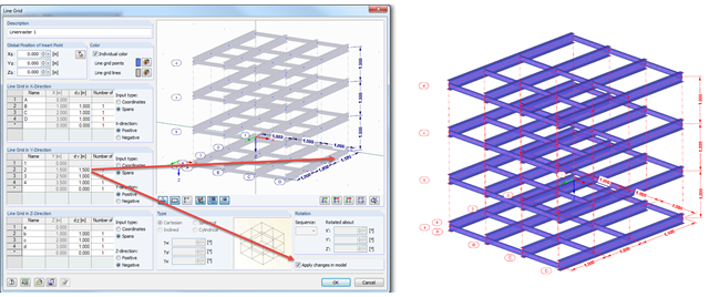
Arranging a model into an axis can provide better visibility, and in addition, the line grid can allow you to apply changes quickly in the model.
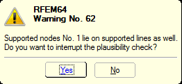
You can define nonlinear supports in RFEM and RSTAB. In RFEM, these are represented by nodal, line, and surface supports. Many customers contact us because of nonlinearities that are apparently not acting as desired. For example, there is a failing line support in a model. Since the structure is statically determined as supported, a linear nodal support is usually added. If the nodal support rests at the start or the end of a nonlinearly supported line, there is no clear definition of the degrees of freedom, so the nonlinearity cannot be considered properly. In this case, RFEM displays a warning message.
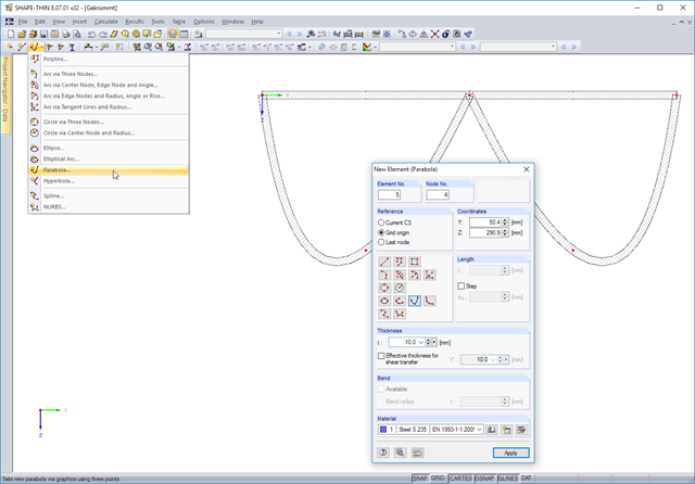
In addition to arcs and circles, SHAPE-THIN 8.xx allows you to model the following curved cross-section parts: ellipses, elliptical arcs, parabolas, hyperbolas, splines, NURBS (non-uniform rational B-Spline).

The determined values for the influence ordinates are displayed as decimal numbers with up to six decimal places by default. This is usually sufficient for the influence lines of internal forces.
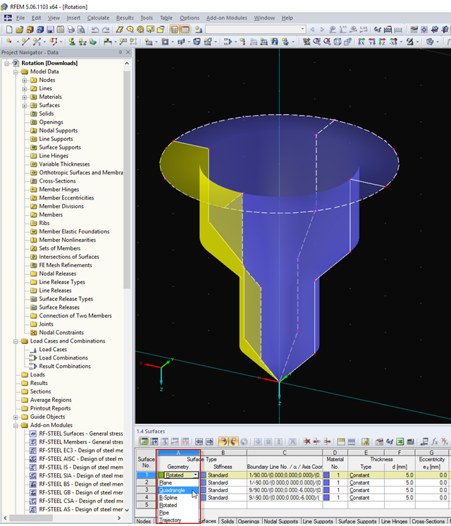
You can quickly model very complex objects in RFEM by rotating lines or polylines. If you need to change the model subsequently, quadrangle surfaces provide an advantage, as they include editable boundary lines.
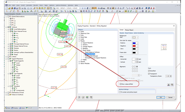
In the case of very small distances between isolines, the labels often overlap, which makes the result documentation difficult. As of RFEM version 5.06, you can select a shifted arrangement of the isoline labels in the Display Properties dialog box. By selecting the "Show values shifted" option, you can easily avoid overlapping the result values in many cases.
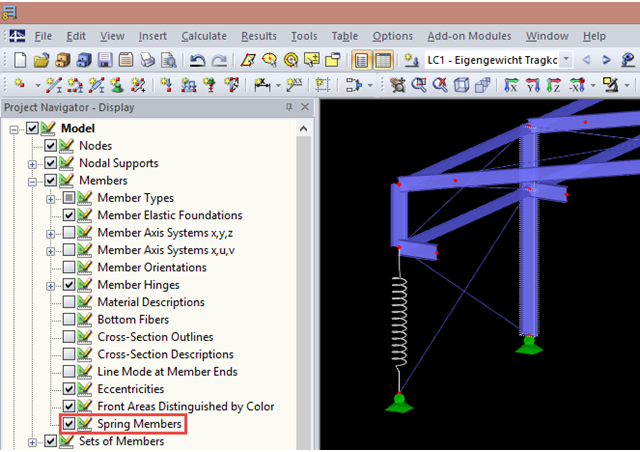
You can display spring members in the Display Navigator. A spring member is displayed as a helix by default. Clear the "Spring Members" check box to display them as normal lines.
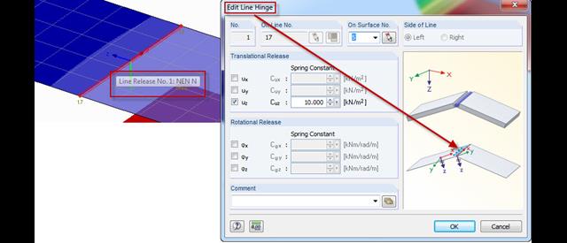
In order to facilitate the selection of the corresponding line release, the axis system of the line release appears when selecting a line release. In the case of a line hinge, the orientation is often different; therefore, the representation has been improved in the pre‑selection for line hinges.

If you want to consider guide objects in the overall view (F8 key or double-click on the mouse wheel) or, for example, in a particular direction of the views, you can enable this option in the settings of the particular guide objects (guidelines, background layers, line grids).

Nodal supports are usually defined with regard to the global axis system. However, it is sometimes necessary to rotate the nodal support. For example, for a floor slab with a pile foundation. For geological reasons, the piles do not rest in the ground vertically, but in an inclined position. Each end point of the piles has a nodal support that can only absorb forces along the pile foundation direction. Therefore, rotating the nodal support is required. Various options for this are described in previous posts.
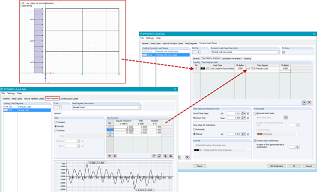
In RF-/DYNAM Pro - Forced Vibrations, you combine static load cases with time diagrams to define the type of excitation of your structure. This way, you can use not only nodal loads, but also use line, surface, free, or generated loads in the time history analysis.
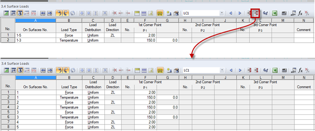
The load tables provide a simple option to control the applied loads. Dividing loads into individual lines is expedient. After dividing loads into the load table, the load data are displayed by a structural element (nodes, members, lines, surfaces, or solids). Thus, the load data analysis of each structural element is facilitated. The load case data can be compressed later.
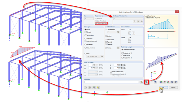
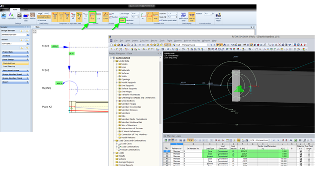
RFEM and RSTAB provide a helpful preview to check the input of member and line loads in the dialog box.

The RX‑TIMBER stand-alone program offers you the option to optimize the lateral-torsional bracing. With this selection, the program iteratively determines the required minimum length of the lateral-torsional bracing.

Everything is online. The same is true for the Dlubal licenses for RFEM 6, RSTAB 9, and RSECTION. This article contains information about using and managing online licenses, reserving licenses, checking the license validity, and moving authorizations between the licenses.
You can now also create concentrated member and line loads in RFEM and RSTAB. This is an extension of the original member/line load function. From now on, you can create several concentrated loads with uniform or user-defined load distribution on a member or a line.